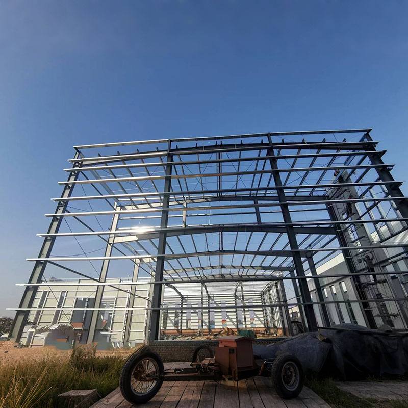

In steel structures, steel beams serve as the building's "skeleton." The connection between secondary beams and primary beams, beam splicing, fabrication methods, and beam stability and strength are key to ensuring the stability of this "skeleton." Today, let's demystify this knowledge with LWY.

1. Overlap Splice: This is the simplest method, like placing one building block directly on top of another. The secondary beam is placed directly on top of the primary beam and secured with welds or bolts. This method is suitable for light loads and offers the advantage of ease of construction, but it increases the height of the structure.
2. Flat Splice: The secondary beam is attached to the side of the primary beam, transferring forces through stiffeners or supports. This connection method reduces the height of the steel structure and is more widely used.
Continuous secondary beams are supported at multiple points, so force transfer and balance must be considered when connecting them to the primary beam. Typically, rigid connections are used, using welding or high-strength bolts to securely connect the secondary beam to the main beam, effectively transferring bending moments. Special structural measures, such as additional steel plates and stiffeners, are implemented at the connection points to ensure stable transmission of forces from the continuous secondary beam to the main beam.
The factory is like a "super-fabrication plant" for Steel Structure, offering numerous advantages for splicing steel beams. The stable factory environment and excellent welding conditions allow for more precise work and easier quality control. Full penetration welds are typically used on the flanges and webs during splicing to ensure joint strength. However, splicing locations should avoid areas of concentrated stress, such as beam supports and areas subject to high loads. The distance between the flange and web welds must be at least 200mm.
When beams are too large to be transported from the factory, they must be spliced on-site. Common on-site splicing methods include bolt-weld and full bolting.
Hot-rolled steel is rolled and formed at high temperatures, resulting in beams with regular cross-sections, such as the common H-beam. These beams offer high strength and are suitable for large-span, heavy-duty steel structures. For example, hot-rolled H-beams are commonly used in roof beams of large stadiums.
Welded composite beams are constructed by welding web and flange plates together, allowing for customizable cross-sections. For example, welded composite beams are particularly effective in beams requiring variable cross-sections. This flexible production method allows for better adaptation to load requirements and can save over 30% of steel compared to other methods.
Cold-formed thin-walled steel is formed by bending at room temperature. Its cross-sectional shapes are complex and diverse, such as C-beams and square tubes. These beams are lightweight, but their thin walls make them susceptible to buckling. Therefore, they are often used in lightweight steel structures, such as roof purlins in buildings.
When a steel beam is subjected to compression, the compression flange may experience lateral buckling, much like a thin bamboo pole bending to one side when pressed. To prevent this, we can increase lateral support and shorten the free length of the compression flange. We can also use a box section or increase the flange width to increase the beam's torsional stiffness.
If the height-to-thickness ratio of the web or flange of a steel beam is too large, wavy buckling deformation will occur. To ensure local stability of the steel structure, transverse stiffeners are installed in the web to prevent buckling due to shear stress, and longitudinal stiffeners are installed to prevent buckling due to bending stress. Furthermore, the flange width-to-thickness ratio must meet regulatory requirements to prevent local instability.
When designing a steel beam, it is necessary to verify bending stresses, shear stresses, local compressive stresses, and other stresses to ensure that these stresses do not exceed the yield strength of the steel. Different steels have different strengths. For example, the strength of Q355B steel is 40% higher than that of Q235B steel. However, when using them, you should also pay attention to whether the welding process of the steels matches.