

Abstract
Floating wind platforms operate in some of the most hostile marine environments on earth, facing combined wave, wind, and current loads that far exceed land-based structural design criteria. The question of whether platforms for floating offshore wind turbines can reliably withstand these extreme conditions is central to the commercial deployment of deep-water wind energy. This analysis examines the design principles, material specifications, fabrication quality measures, and certification pathways that determine a platform's survivability across a 25-year service life.
From hydrodynamic load modeling to weld inspection protocols, the engineering decisions made during design and construction directly influence how a floating structure performs under hurricane-force winds, rogue waves, and cyclic fatigue loading. The evidence from recent demonstration projects and classification society approvals provides meaningful benchmarks for evaluating platform resilience.
Select any section to navigate directly:
1. How Design Verification Addresses Extreme Load Scenarios
A floating wind platform must simultaneously resist static loads from the turbine and dynamic loads from waves, wind, and currents. Unlike fixed-bottom structures that transfer loads directly to the seabed, floating platforms rely on buoyancy, ballast distribution, and mooring tension to maintain stability. This makes the structural design process fundamentally different, requiring coupled analysis of hydrodynamic, aerodynamic, and structural responses.
Classification societies such as DNV and ABS have established dedicated standards for floating wind structures. DNV-ST-0119 provides the governing framework for design, construction, and in-service inspection, covering ultimate limit states, fatigue limit states, and accidental limit states. The standard requires that platforms demonstrate structural integrity under the 50-year return period environmental conditions specific to the deployment site, with safety factors applied to both loads and material resistance.
Key Design Load Cases
- Extreme wave loading combined with maximum wind thrust at the turbine rotor.
- Fatigue loading from wave cycles accumulated over 25 years of continuous operation.
- Mooring line failure scenarios that redistribute loads across remaining lines.
- Accidental collision loads from service vessels during maintenance operations.
Recent platform concepts demonstrate how design optimization reduces structural weight without compromising safety margins. The X100 platform developed by X1 Wind and Technip Energies combines tension-leg platform principles with semi-submersible buoyancy, achieving a primary steel weight of approximately 1,500 tons for an 8.5 MW turbine with a 160-metre rotor diameter[reference:0]. This represents a weight reduction of 30 to 50 per cent compared with earlier European demonstration platforms of similar scale, achieved through a tripod-shaped geometry that distributes loads more efficiently across the structure.
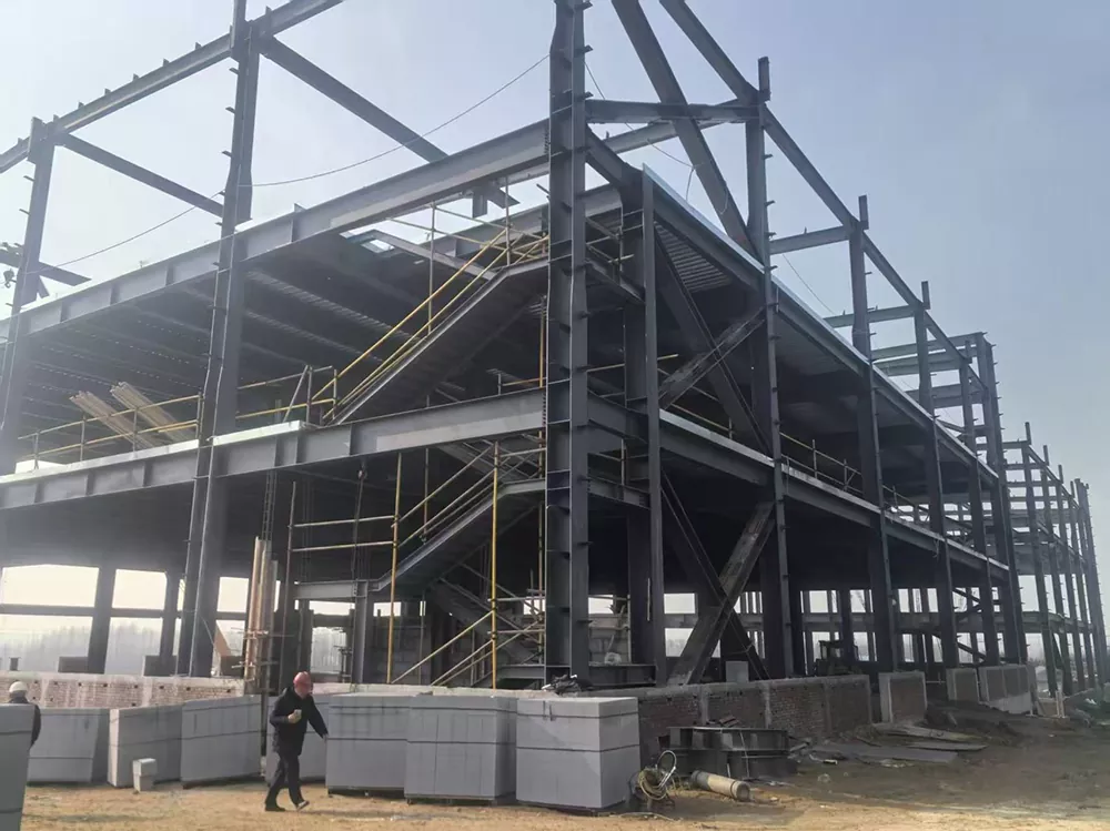
2. Material Selection for Corrosion and Fatigue Resistance
The marine environment imposes two primary degradation mechanisms on steel structures: electrochemical corrosion and fatigue cracking. Both must be addressed at the material specification stage, because field repairs on a platform positioned 20 kilometres offshore are measured in vessel days and weather windows.
Atmospheric salt loads in offshore zones are classified as C5-M under ISO 9223, the most severe corrosion category. Plain painted steel can fail within a few years under these conditions. The fabrication of durable platforms begins with selecting steel grades that maintain toughness at low temperatures, typically Q355B, Q355D, S355, or A572 equivalents with certified impact properties[reference:1]. These grades balance weldability with the yield strength needed for primary structural members.
| Protection Layer | Specification | Function |
|---|---|---|
| Surface preparation | Shot blasting to Sa 2.5 (ISO 8501-1) | Removes mill scale and contaminants for coating adhesion |
| Primer | Zinc-rich epoxy | Provides sacrificial cathodic protection at coating defects |
| Intermediate coat | High-build epoxy | Barrier against moisture and chloride ion penetration |
| Topcoat | Polyurethane or polysiloxane | UV resistance and colour stability |
| Hot-dip galvanizing | ISO 1461, minimum 85 μm zinc | Used for smaller components and walkways |
For submerged components and splash zone areas, cathodic protection through sacrificial anodes or impressed-current systems supplements the coating system. Connection details must be designed for compatibility with these systems, including provisions for weldable anodes where specified. Total coating system thickness typically exceeds 240 micrometres for large primary structures, providing a service life compatible with the platform's 25-year design life.
Fatigue design requires attention to weld detail categories and stress concentration factors. Tubular joints, which are common in floating platform truss structures, experience hot-spot stresses at the intersection of brace and chord members. Finite element analysis combined with classification society S-N curves allows engineers to verify that cumulative fatigue damage remains below acceptable limits over the service life.
3. Fabrication Quality and Structural Integrity
Design calculations are only as reliable as the fabrication that realizes them. Weld quality, dimensional accuracy, and material traceability directly determine whether a platform achieves the structural performance predicted by analysis.
All welds in primary structural members should be executed by certified welders working to qualified procedures. EN ISO 9606 and AWS D1.1 are the two most widely applied welding qualification standards for offshore steel structures. Weld procedures must be qualified before production begins, with test pieces subjected to mechanical testing and, where required, macrostructural examination.
Non-Destructive Testing Requirements
- 100 per cent ultrasonic or radiographic inspection of butt welds in primary members.
- Magnetic-particle inspection of fillet welds on a sampling basis agreed with the client.
- Dimensional verification of bolt-group spacing and flange flatness using fabrication jigs.
- Coating thickness measurement at designated check points after application.
- Material certificates traceable to each plate and section used in fabrication.
Dimensional control during fabrication prevents costly offshore rework. Fabrication jigs and check fixtures hold critical dimensions within tight tolerances, ensuring that platform modules fit together correctly when assembled at the quayside or offshore. Bolt holes for tower connections, crane pedestals, and mooring equipment must align precisely to avoid field drilling or modification.
Modular fabrication strategies further improve quality control by concentrating welding activity in a controlled factory environment. The Aikido platform, for example, consists of thirteen modular steel components that can be fabricated at existing offshore wind or steel fabrication sites and then assembled using pin joints without major welding at the quayside[reference:2]. This approach reduces the risk of weld defects in difficult field conditions and shortens assembly time.
4. Evidence from Demonstration Projects and Certification
The most credible evidence for platform survivability comes from independently verified design assessments and operational data from demonstration projects. Classification society certifications provide structured confirmation that a platform design meets recognized safety and performance standards.
BW Ideol's 15 MW+ floating platform received Basic Design certification from DNV in May 2025, following earlier certifications for the Floatgen, Hibiki, and Eolmed projects. The platform is compatible with turbines in the 14 to 16 MW range and is being scaled up to 22 MW, with adaptability to a wide range of metocean conditions from moderate to challenging environments[reference:3]. This track record of successive certification across multiple projects demonstrates that the design methodology has been validated under independent review.
Odfjell Oceanwind's Deepsea Star, a column-stabilised semi-submersible steel platform with a centre tower, received Basic Design Approval from DNV covering use with the Siemens Gamesa SG 14-236 DD 15 MW turbine in a wide range of offshore conditions. The approval verified the strength and grade of steel material for the main structure, corrosion protection, stability, mooring, and marine systems[reference:4]. The design has also been selected for the 100 MW Salamander floating wind project in Scotland.
| Platform Concept | Developer | Certification | Turbine Class |
|---|---|---|---|
| X100 | X1 Wind / Technip Energies | DNV Statement of Compliance | 8.5 MW, 160 m rotor |
| 15 MW+ Platform | BW Ideol | DNV Basic Design | 14–16 MW, scalable to 22 MW |
| Deepsea Star | Odfjell Oceanwind | DNV Basic Design Approval | 15 MW and larger |
| AO60 | Aikido Technologies | ABS Statement of Maturity | 15 MW |
The X100 platform's environmental approval for the PlemCat test site in the Mediterranean Sea adds a further dimension to the evidence base. The approval confirmed compatibility with marine environmental protection requirements, including the use of vertical synthetic mooring lines that reduce seabed footprint and underwater noise compared with conventional catenary systems[reference:5]. The platform will operate in offshore conditions for several years, generating performance data that supports final prototype certification.
5. Frequently Asked Questions
What wind and wave conditions must a floating platform survive?
Platforms are typically designed for the 50-year return period conditions at their specific deployment site. This may include wave heights exceeding 15 metres, wind speeds above 40 metres per second, and combined loading from waves, wind, and currents acting simultaneously.
How is fatigue life verified for welded tubular connections?
Fatigue assessment combines finite element analysis of hot-spot stresses with classification society S-N curves. The cumulative fatigue damage over 25 years must remain below the design fatigue factor, which typically ranges from 1 to 3 depending on the criticality of the connection.
What steel grades are used for primary structural members?
Common grades include Q355B, Q355D, S355, and A572 equivalents with certified low-temperature impact properties. Material certificates are provided for every plate and section, allowing full traceability through the fabrication process.
How long does the corrosion protection system last?
A properly applied marine coating system with cathodic protection is designed to match the platform's 25-year service life. Hot-dip galvanizing provides decades of maintenance-free protection for smaller components such as walkways and access platforms.
Can platforms be assembled at existing port facilities?
Modular designs specifically target existing port infrastructure. Components are fabricated at steel fabrication yards, transported to a quayside assembly area, and joined using structural connections that minimize or eliminate welding at the port.
The fabrication of platforms for floating offshore wind turbines is carried out by LWY Steel Structure, which produces marine-grade steel components at its Qingdao facility with an annual processing capacity exceeding 20,000 tons.