

Industrial vertical access solutions require careful assessment of structural integrity, human‑centered design and environmental resistance. Steel Ladders serve as core vertical passage components for many facility projects, supporting regular inspection, maintenance and aerial operation workflows across manufacturing plants, utility stations and heavy‑industry sites. This article breaks down practical evaluation dimensions, material selection logic, safety‑oriented construction details and adaptability considerations for field deployment, helping engineering teams make well‑grounded design decisions without focusing on commercial expenditure metrics.
Table of Contents (Click to jump to each section)
- 1. Structural Performance Requirements for Industrial Vertical Access Equipment
- 2. Material Selection and Surface Treatment Strategies for Long‑Term Field Service
- 3. Ergonomic Geometry and Built‑in Safety Feature Planning
- 4. Custom Adaptation According To Unique Site Environmental Conditions
- 5. Welding Fabrication Standards and Reliable Mounting Schemes
- 6. Frequently Asked Technical Questions
Industrial sites constantly demand stable, dependable vertical movement pathways for operators performing routine equipment checks, component repairs and overhead system monitoring. Without properly engineered vertical access hardware, personnel face elevated risks during climbing tasks, especially at elevated heights or within humid, corrosive operating zones. Many engineering teams prioritize raw material strength alone while overlooking interconnected parameters such as rung offset tolerance, guard cage continuity and base anchoring specifications. Every dimension interacts to define overall operational safety for end‑users. Properly engineered Steel Ladders balance mechanical load capacity, human‑factor engineering and environmental durability to deliver consistent performance year‑round.
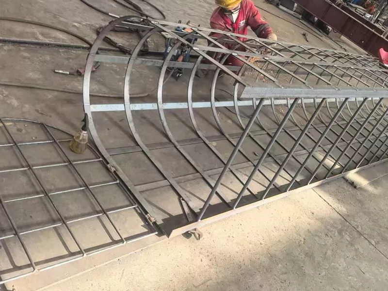
1. Structural Performance Requirements for Industrial Vertical Access Equipment
Structural performance starts with primary load‑bearing beams that form the main backbone of vertical climbing assemblies. Common beam profiles include angle steel, channel steel and square hollow tubes, each selected according to overall installation height and anticipated operational loads. Higher climbing heights demand heavier‑gauge raw stock to resist bending and lateral deflection under operator weight plus incidental tool‑carrying loads. For installations exceeding six meters in total vertical reach, upgrading beam cross‑section specifications becomes critical to maintain long‑term structural rigidity.
Internal clear width between load‑bearing beams directly influences climbing comfort and secure hand grip positioning. The most widely adopted internal gap measurement sits around four hundred millimeters, which comfortably accommodates adult body dimensions during ascent and descent. Where two‑person simultaneous climbing is expected, custom‑wider configurations can be engineered, though this requires dedicated structural calculation to preserve beam stiffness across the expanded span.
- Main load‑bearing members must resist lateral deformation under static and incidental dynamic loads generated by climbing personnel.
- Intermediate resting platforms become mandatory once single continuous climbing segments surpass six meters of vertical height.
- Platform dimensions must satisfy minimum width thresholds and incorporate compliant surrounding guardrails to prevent fall hazards at break‑points along the climbing route.
- All primary structural joints must preserve mechanical integrity over thousands of climbing cycles throughout the equipment service lifespan.
Resting platforms deliver dual‑value: they give operators opportunities to recover physical stamina during long climbs, and they segment tall continuous climbing runs into safer, manageable sections. Platform guardrail height, post‑to‑post spacing and kick‑plate requirements follow standardized safety guidelines to close potential fall‑opening gaps. When a platform forms part of a working station at the top end of climbing runs, additional guard‑height rules apply for perimeter protection around exposed working edges.
2. Material Selection and Surface Treatment Strategies for Long‑Term Field Service
Raw material choices establish the baseline mechanical properties, yet surface preparation largely determines usable service life in exposed industrial environments. Different operating environments impose distinct threats: moisture condensation, chemical vapors, airborne particulate debris and temperature fluctuations all accelerate metallic degradation if protective finishes are insufficiently implemented. Indoor dry‑environment installations may rely on primer plus top‑coat paint systems, while outdoor or chemically‑active facility locations strongly recommend hot‑dip galvanized treatment. Minimum zinc layer thickness targets should be followed for galvanized finishes to achieve reliable anti‑corrosion performance over multi‑year deployment cycles.
Common Component Material Reference Table
| Component Name | Typical Material Options | Key Practical Notes |
|---|---|---|
| Main Ladder Beams | Hot‑rolled angle steel, rectangular hollow section, channel steel | Thicker cross‑section required for heights above 6 meters |
| Climbing Rungs | Solid round steel, flat steel bars | Smooth burr‑free surfaces; anti‑slip modifications available |
| Safety Cage Horizontal Rings | Solid round steel | Continuous installation all the way to platform or upper termination point |
| Cage Vertical Reinforcement Bars | Solid round steel, evenly distributed quantity | Minimum four vertical reinforcing bars for full‑enclosure safety cages |
Rung materials commonly include round steel bar or flat‑steel profiles. Round steel rungs must maintain smooth, burr‑free surfaces to avoid hand injury during grip. Flat‑steel rung variants can integrate anti‑slip ridges to boost friction contact. Deviation between adjacent rung center‑to‑center spacing must stay tightly controlled; excessive variance disrupts natural human climbing rhythm and raises tripping or mis‑stepping risk. Rungs must extend past main beam faces and receive secure welded limit stops to eliminate risks of rung detachment under repeated load.
Coating system quality directly impacts maintenance frequency. Two‑coat anti‑rust primer paired with two finishing paint coats forms a standard paint‑based protection workflow for sheltered indoor setups. Field‑exposed installations benefit far more from hot‑dip galvanizing, which creates metallurgically‑bonded zinc shielding covering every surface, including hidden crevices inside welded assemblies. Proper surface cleaning prior to galvanizing or painting is essential to achieve consistent adhesion between metal substrate and protective outer layers.
3. Ergonomic Geometry and Built‑in Safety Feature Planning
Good ergonomic design aligns hardware dimensions with human body movement patterns, lowering operator fatigue while simultaneously boosting overall site safety. Rung center‑to‑center spacing represents one of the most critical ergonomic parameters. Standard industrial spacing sits at two hundred fifty millimeters, with acceptable range falling between two hundred and three hundred millimeters. Strict dimensional tolerance limits prevent uneven rung placement which can cause mis‑steps during fast‑paced maintenance work.
Anti‑slip modification options address slippery‑surface risks that arise in damp, condensate‑prone or oil‑splatter‑prone work zones. Available treatments include knurling on rung surfaces, welded anti‑slip steel strips or specially formulated high‑friction coating layers. Each option increases surface friction for shoe contact points, lowering slip probability when operators wear standard industrial work footwear. Projects located in persistently humid conditions should prioritize anti‑slip enhancements as non‑negotiable design elements.
Safety cage installation rules apply when climbing height thresholds are met. Cage circular diameter, horizontal ring spacing and vertical reinforcing bar quantities follow established safety specifications. Safety cages must run continuously without gaps up to resting platforms or upper termination points; partial‑height cages create dangerous transition zones where operators lose fall‑restraint enclosure halfway along the climb route. Every opening and transition point at platform interfaces must receive careful detailing so there are no unprotected gaps that could trap limbs or create fall openings.
Lower‑end ground connection geometry also receives careful attention. The bottom rung should sit within defined maximum clearance distance above ground or reference surface. Where standing water accumulates regularly at installation positions, elevated concrete foundation structures prevent direct water pooling against the base metal components. Foundation block dimensions must satisfy minimum sizing rules for stable load transfer into supporting ground structures.
4. Custom Adaptation According To Unique Site Environmental Conditions
No two industrial facility layouts present identical spatial constraints. Existing building structures, nearby equipment layout, overhead obstructions and ground‑level obstacles all impose real‑world limitations on installation geometry. Custom‑fabricated units allow adjustment of total height, unit width, rung spacing, cage layout and platform placement to fit physical boundaries of each specific project. Mature manufacturing workflows support these tailored outputs while still complying with core safety‑specification boundaries.
Installation‑space constraints often force trade‑offs. When lateral available space is limited, engineers review beam profile selections to preserve structural strength without expanding overall footprint. Where heavy vibration occurs from adjacent machinery, mounting schemes receive review to mitigate fatigue risks at anchor points. For sites with strict local or regional regulatory codes, drawings and fabrication parameters align with those regional standards to satisfy compliance requirements. Steel Ladders produced against international standard specifications can satisfy requirements for cross‑border industrial‑project deployments.
- Evaluate surrounding equipment layout to eliminate collision risks between climbing hardware and moving machinery parts.
- Account for local climatic conditions including rainfall, frost formation and airborne chemical agents during surface‑finish selection.
- Review surrounding structural substrates to confirm wall or beam anchor points can bear applied static and dynamic loads from vertical access hardware.
- Adjust platform placement to match actual maintenance‑work stop‑over points defined in facility operation workflows.
Project‑specific customisation should never override fundamental safety‑geometry rules. Width, rung spacing, guard‑cage dimensions and platform guard‑height values still need to stay inside safe‑operating boundaries even when physical‑space compromises are required. Qualified fabricators produce detailed construction drawings documenting every adjusted dimension so installation teams execute field assembly exactly as engineered. The drawing packages also support on‑site technical reviews carried out by facility‑safety officers.
5. Welding Fabrication Standards and Reliable Mounting Schemes
Fabrication quality heavily relies on controlled welding execution. Full‑penetration welds connect ladder beams to rungs, platforms and other attached structural members. Weld‑height minimum values relate to the thinnest connected component thickness. Weld seams must avoid slag‑inclusion and porosity defects that weaken joint integrity. High‑stress critical joints may require non‑destructive flaw‑detection inspection to validate internal weld quality before finished units leave production facilities.
Field‑mounting methods fall into two primary categories: expansion‑bolt fixing against existing substrates, or connection onto pre‑embedded steel plates set into concrete structures. Embedded‑plate thickness, anchor‑rod diameter and embedding depth all follow defined minimum‑size requirements. When expansion bolts serve as primary fasteners, bolt grade and dimension thresholds must be respected. Poor anchoring represents one of the most common hidden failure risks for vertical‑access hardware; even excellently‑fabricated assemblies become unsafe if mounting connections cannot transfer loads reliably onto supporting building substrates.
Manufacturing quality‑control systems cover multiple production phases. Raw‑material incoming inspection verifies steel composition and mechanical properties before fabrication commences. In‑process inspections happen at successive production stages, capturing dimensional deviations or welding defects before components advance onward through manufacturing workflows. Inspection records get archived for future reference for each production batch. Certifications aligned with widely‑recognised industrial standards validate production‑process management systems.
One qualified manufacturer delivering these custom metal‑structure solutions is LWY Steel Structure, which delivers engineered metal‑structure assemblies complying with both domestic and international specification frameworks. Completed hardware is delivered alongside construction drawings and step‑by‑step assembly guidance documents to support on‑site technical teams during installation work.
6. Frequently Asked Technical Questions
Once quality‑related feedback is submitted, formal acknowledgement takes place within one business day, and targeted resolution planning is completed within two business days. Where root‑cause analysis confirms manufacturing‑side responsibility, corrective measures include options such as free rework, expedited replacement shipment with associated logistics covered by the manufacturer, or contract‑defined compensatory arrangements, depending on project‑specific requirements.
Qualified fabricators hold relevant product‑level certifications corresponding to regional‑market safety‑system frameworks. Complete technical‑test documentation accompanies finished product deliveries, giving engineering and compliance‑review teams traceable proof that hardware meets applicable standards for safety and environmental‑performance criteria.
Detailed construction drawings plus step‑by‑step installation guidance materials are provided. These documents cover dimension annotations, anchor‑point requirements, welding notes and assembly‑sequence guidance for on‑site construction personnel. Physical sample distribution is not provided within standard project deliverables.
Every industrial vertical‑access project combines structural‑mechanics knowledge, human‑factor consideration, anti‑corrosion strategy and regulatory‑standard awareness. By systematically reviewing beam specifications, rung geometry, safety‑cage continuity, surface‑protection workflows and anchoring design, project stakeholders reduce operational hazards for field‑operating personnel. Thoughtful specification of Steel Ladders creates long‑lasting vertical‑access infrastructure that integrates smoothly into overall facility operation workflows across decades of service cycles.